Since there are so many detailed tutorial about compute shaders so I’m not going to explain every line of the code. Here are just some basic concept.
Compute Shader
Idea of Compute Shader :
CPU assign workload to GPU to take advantage of GPU‘s fast parallel processingIn Unity, codes that run on CPU are called C# script.
Codes that run on GPU are called shader,
no matter the code is for rendering or just calculating something.
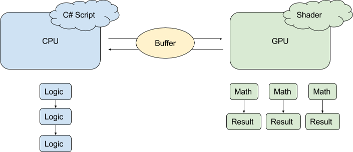
Example:
You want GPU to modify a texture. The RGBA value of each pixel on the texture are calculated using a function, which the code is written inside a compute shader.


Steps:
- Texture is 512*512, CPU creates it and put it to buffer.
- Based on your hardware, you want GPU to process 8*8*1 pixels in parallel
-> define numthreads(8,8,1) in GPU side - Therefore CPU need to dispatch 512/8 * 512/8 * 1 thread groups to GPU, so that all pixels are processed
- GPU process the result colors of the pixels and save them in buffer.
- CPU grabs the data in buffer and assign the texture to a material. This is what you see in the picture above.

Compute Buffer (Array of Structs)
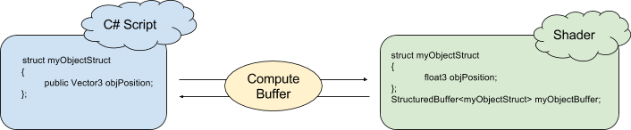
Idea of Compute Buffer:
A memory space for data between CPU and GPU

Example:
This example doesn’t involve using compute shader. Just compute buffer, with normal shader.
You have many sphere objects (but here we just have 2). You want the color of vertex on the black plane becomes red when any spheres come near them.
Steps:
- For each sphere we need it’s Transform.Position, which is a 3-float values. And 1 float = 4 bytes, so the buffer size for EACH sphere is 3*4 = 12 bytes.
- Both CPU and GPU has the same struct.
-> Since data flow from CPU to GPU, CPU defines the total buffer size to be 2*12 bytes. - CPU send data to GPU‘s array of struct in each frame.
- Shader grabs the position values and calculate the distance between the vertex and sphere positions in vertex shader. This is why you see red color round the spheres.
———
*Normally data flow is:
CPU -> GPU (Normal Shader)
CPU <-> GPU (Compute Shader)
What’s happened to CPU <- GPU (Normal Shader)? This is because normal shaders are for rendering so it makes sense that GPU won’t give data back to the CPU! If you still want to do it e.g. for debugging / grabbing vertex data after render pipeline, please look here:
https://dexint.wordpress.com/2017/06/16/good-for-shader-debug-uav-randomwritetarget/
Visit here for some examples: https://github.com/cinight/MinimalCompute
